Showing posts with label rear. Show all posts

Saturday, 30 April 2022

E90 318d: New rear caliper! [Reconditioned exchange part]

Rear O/S calliper was sticking on this 2005 E90. A re-conditioned genuine unit was sourced for just £45 with the old one being returned in exchange.

Not a bad hours work... remember to prime the new calliper with fluid and it hardly needs bleeding.

Thursday, 1 April 2021

F10 530d: Water in Battery well / Bootwell / Trunkwell - where is it leaking?

I lifted the boot/trunk floor to jump-start a friends car and noticed that my battery well / spare-wheel well is full of dirty water.... oh dear. I’ve got a leak... but where? Boot seal? Bottom of the rear windscreen? There was a second aerial / antenna fitted in the roof that I removed, so figured it might be leaking through there and running down the C-pillar into the boot, but no water marks in the headlining or signs of ingress... Think I will have a proper look this weekend and try get to the bottom of it!


Thursday, 3 December 2020

F10: Rear Shock Absorber / Strut / Spring Replacement [GUIDE]


Time to do the rear struts and springs on the 530d F10 this week as one damper has been leaking and while doing my tyres last week I noticed the spring has now broken at the bottom so this is now an urgent job. I picked up a pair of used complete struts (spring, damper and top-mount) from eBay for just £100. They are from another 530d and claim to be from a low mileage car. Well, they look a lot lower mileage than the ones I'm taking off lets put it that way and appear to be in pretty good condition. I get a lot of stick for constantly using second-hand genuine parts, but I still prefer this to buying new spurious parts where I can and have never had an issue!

GUIDE:

* This is not a difficult or time-consuming job, but will require a bit of brute force. *

1. First the rear seats need to come out. Lift the seat squab up at the front and detach it from the push-studs, press the seat-belt receivers through the recesses and lift the squab out. Next lift the seat-back upwards until it is free of the hooks at the top and lift that out, being careful of the door-sill paintwork and sliding it through the seat-belts. [You could always unbolt the seat-belts at the base using a T45-Torx socket to make this easier, but it's not essential].

2. The parcel-shelf now needs to come down in order to access the strut-top mount bolts in the shock-turrets. Remove the C-pillar trims by prizing out the plastic caps labelled 'Airbag' from the trim and removing the screw using a T25-Torx socket. Now carefully pull away the C-pillar trims and put to one side. Remove the five push-pin clips from the front edge of the parcel-shelf by levering the button in the centre upwards and pulling the plastic pin out. The studs can now be levered out. The parcel-shelf is now free to pull forwards and can be rested where the seat-back would be. [Remove the wiring-connectors to the speakers, but these should pop out by themselves anyway].

3. Lift the car and remove the corresponding wheel. [There is no need to be getting under the car for this job, so a jack and axle-stand is fine].

4a. The track-strut (pictured) needs to be moved out of the way to access the bottom strut bolt so first remove the plastic clips holding the E-brake wire-harness to the track-strut by levering them open at the bottom with a flathead-screwdriver and separating them from the strut. The wire-harness can be moved out of the way.

4b. Remove the bolt holding the inner end of the track-strut using an 18mm wrench. Pull the track-strut down and rotate it so it is pointing out of the wheel-arch. You now have plenty of room to get at the bottom strut bolt and lift the shock out.

5. Remove the bolt holding the bottom of the strut to the hub using a 21mm wrench.

6. Lift the triangle flap in the foam underneath where the parcel-shelf was to expose the studs to the strut-top mount and remove the three nuts using a 13mm wrench.

7. Wiggle the bottom of the strut free from the hub and the entire strut assembly is now free to be removed. It should be able to be lowered through the remaining suspension parts and to the rear of the car until it is free to be removed.

** IF YOU ARE CHANGING THE SPRING / TOP-MOUNT OR SWAPPING THESE ONTO A NEW STRUT THEN DO THIS NOW** [See this post for guide].

8. Make sure the new strut has the top-mount in line with the old one you removed by lying them next to each other and checking the bottom bolt-eyelet and triangle marking on the top-mount match up. [The triangle marking on the top-mount should face towards the back of the car with the bolt-eyelet facing the centre, or with the triangle marking facing you the bolt-eyelet should be pointing to the right for O/S (right-side) and left for N/S (left-side)].

9. Lift the new strut back up through the suspension and line it up into the strut-turret. [Triangle marking on top-mount facing rear of car] and screw the three 13mm nuts back on a few threads.

10. Lever the hub downwards until it meets the bolt-eyelet at the bottom of the strut meets its recess on the hub and screw the 21mm bolt back in about half-way.

11. Fully tighten the three 13mm nuts on the strut-top mount.

12. Fully tighten the 21mm bolt through the bottom of the strut.

13. Replace the track-strut / wheel as a reversal of steps 3 and 4.

14. If you are doing both sides then repeat steps 3 - 13 for the opposite side.

15. Replace the parcel-shelf, trim and rear seat as a reversal of steps 1 and 2.

Sunday, 26 January 2020

E28 5er - Interesting unknown rear wing/spoiler... Hartge maybe?

A lovely barn-find shot of an E28 528e in the USA, but on closer inspection it sports a striking rear-wing/spoiler that I have never seen before. Who makes this piece? On first impression I would say one of the period Euro-tuner firms like Zender or Hartge, but after a bit of research I can't find an identical one. The chrome-trim makes it look as if the spoiler was fitted later on though and the car is not a tuner model. Perhaps someone can shed light on this spoiler's origin?


Hartge lay claim to a few E28 aero-parts and a I can find a couple of similar rear-wings, pictured below. The upper one is a rounded type and I am not sure is definitely made by Hartge though the badge suggests it is, and the second pic shows a Hartge developed E28 with their own rear-wing fitted, very similar to the one at the top but not quite as tall and curved on the top-edge not flat. It could well be that it is a similar version of this same spoiler and still made by Hartge, but I cannot find it.


Sunday, 19 February 2017

F10: Rear Parcel-Shelf Swap / Replacement

The original parcel-shelf was in a sorry state, with several rectangular slots cut in it where Police lights had been fitted. The two in the below picture were glaring at me every time I looked in the rear-view mirror and third, twice the size and facing the rear, could be seen clearly from outside. Despite not being one of the first things to get replaced, it became my biggest concern with the interior and has ended up being the piece that has made the most difference to the car's appearance.

A mint and very clean  replacement was £60 from eBay and came with the speakers, grilles and all trim pieces, handy as mine was missing some.


FITMENT:

1. Remove the rear-seat squab by pulling the front edge up sharply at either side and sliding it forward.

2. Remove the 3 bolts holding the bottom-end of the rear seat-belts to the body using a T45 Torx-socket.
3. Remove the rear-seat back-rest by undoing the 2 bolts holding the bottom brackets in place using a T45 Torx-socket and lifting it vertically up off the upper brackets.
4. Remove the 5 plastic-clips holding the leading-edge of the parcel-shelf by prising the centre-pin out with a flat-screwdriver [or ideally a trim-tool] and then prying the clip out.

5. Loosen both of the C-pillar trims. They are only clipped on and should pop off easily enough at the bottom. They do not need to be completely removed, just loose enough to allow the lip at either side of the parcel-shelf to slide in and out.

6. Slide the parcel-shelf forward partially, pop the seat-belts through the apertures and disconnect both speaker wires. The parcel-shelf can now be fully removed.
7. Swap trims/speakers over to new parcel-shelf.
8. Reverse steps 1 - 6 to refit.


Friday, 2 October 2015

E60: Replacing Rear Rose-Bushes / Lower Ball-Joints

These are the main joint where the rear wheel-hubs attach to the trailing-arms and are a pretty common replacement on high mileage 5 and 7 series. They were the advisories I got on the MOT in February, so thought I should get them done before the nice weather ends.

DIFFICULTY - 6/10 This is not a long or complicated job, but is quite labour intensive.

** YOU WILL NEED: A dedicated removal / installation tool. These are available on eBay [here] for just under £40 and work for all modern 5, 6, 7, X5 and X6 rose-bushes. These are all copies of the BMW special tools listed here on TIS.

The rose-bush is item 2 in the diagram.

1. Lift car, remove rear wheel, support on axle-stand.

2. Unbolt the anti-roll bar link from the trailing-arm using an 18mm open/ring spanner on the nut from underneath, while holding the stud from turning using a T40 Torx socket through the centre of the spanner.

3. Loosen the long bolt that holds the trailing-arm to the wheel hub [5] using a 24mm wrench on the nut and an 18mm wrench on the bolt head. [A long breaker-bar is advisable on the nut.]

4. Loosen off the eccentric-bolt on the trailing-arm [11] using an 18mm wrench on the bolt head and a 21mm wrench on the nut. [Be careful not to turn the bolt and alter the alignment as it's hard to get back.]

5. Loosen off the other bolt on the trailing arm [9] using an 18mm wrench on both the nut and bolt head.

6. Fully remove the 24mm nut [6] and long bolt [5] from the wheel-hub. [The bolt will likely need knocking out with a drift.]

7. Remove the bolt holding the push-rod to the wheel-hub [7] using an 18mm wrench.

7a. (O/S trailing-arm only) - Disconnect the suspension-angle sensor from the trailing-arm using a 10mm wrench and 10mm open-end spanner.

8. Lever the trailing arm down so it is clear of the wheel-hub and the push-rod [4] can be removed.

9. Remove the retaining-ring [3] from the rear face of the rose-bush. [It will likely be well seized in place and need splitting with a grinder / cut-off tool before knocking out in two pieces.]

10. Set up the removal-tool either side of the rose-bush with the largest mandrel on the receiving side and the smallest mandrel on the pushing side, ensuring the pushing side is completely flush to the rose-bush face. [Some of the rose-bush rubber boot may need cutting off to ensure this.]

11. Tighten up the removal-tool using a 19mm wrench on either side until the bush pops out of the wheel-hub. [Rotating the receiving mandrel round so the notched area can be viewed from underneath shows the progress of the bush coming out.] [The bush may well need some heat treatment if it is seized, or you can have a go at splitting it if you are brave enough.]

12. Place the new rose-bush into the hub, ensuring it is straight to the collar and will go in evenly. [The bush always slots it from front to rear, with the retaining ring on the rear face.]

13. Set up the removal-tool on the new rose-bush with the largest mandrel on the receiving side again and the mid-sized mandrel on the pushing side. [The notched side of the receiving mandrel will need rotating so it fits flush past the back of the brake disc. This is essential to keep the threaded-bar / bush straight.]

14. Tighten up the removal-tool with two 19mm wrenches until the bush is fully seated in the collar. [The bush should slide in pretty easily, if it resists then it is not going in straight. A small amount of copper grease can be rubbed round the bush to aid it, but be very sparing.]

15. Fit the new retaining-ring to the rear face of the rose-bush.

16. Refit the push-rod and trailing arm etc. as a reversal of steps 8 to 1.

** For correct re-alignment of suspension geometry see this post. **

Sunday, 8 February 2015

E60: Replacing the Rear Trailing-arm / Bushes

REMOVAL:
  1. Jack car, remove wheel.
  2. Remove anti-roll bar link [14] by undoing both the upper and lower nut. Upper nut is 16mm and you need to hold the threaded-bolt by inserting a T30-Torx socket down the end of bolt itself. Lower nut is 18mm and the bolt-end is held by a T40-Torx. Use an open-ended spanner or place a ring-spanner over the Torx-socket before inserting it.
  3. Loosen the eccentric-bolt [11] that aligns the rear suspension, making a note of its position. This is the bolt connecting the trailing-arm to the subframe lowest to the rear of the car. The bolt-head is 18mm and the nut, to the rear, is 21mm.
  4. Loosen off the front bolt [9] connecting the trailing-arm to the subframe using an 18mm socket and spanner. You do not need to remove the hard plastic cover next to it, there is just enough room to hold the obscured bolt with a spanner.
  5. Loosen off the long bolt [5] connecting the trailing-arm to the wheel-hub. The bolt-head is 18mm again and the nut, to the front, is 24mm.
  6. Fully remove the 3 bolts and wiggle the trailing arm out, usually from the subframe end first. The bolts may need helping out with a drift and hammer.
REPLACING BUSHES:
Replacing the rubber-bushes and refitting your existing trailing-arm is the cheapest option. The bushes are really tight in the arm and the old ones can be removed by any means necessary - cutting, burning, whatever gets them out. The new bushes however, are nigh on impossible to fit and will likely need shoving in with a hydraulic-press. Your local garage or mechanic mate will do this for buttons. If your on your own at home, as I was, then replacing the whole arm with bushes already in will save a lot of hassle.


REFITTING:
  1. Offer the trailing-arm up, wheel-hub first, and reinsert the long bolt [5] through the hub, loosely screwing the nut [6] on a few turns.
  2. Manoeuvre the arm up to slide the foremost bush back into the subframe mount and reinsert the bolt [9], screwing the nut [10] on a few turns. The arm may need a bit of twisting and jimmying to get in due to the geometry of the raised suspension.
  3. Manoeuvre the trailing-arm up to fit the rearmost bush back into the subframe mount. This will be difficult and you will likely need a second car-jack and a fair bit of working to get it in so the eccentric-bolt will slide through. Reinsert the eccentric-bolt [11] and tighten it up so it is reasonably tight.
  4. Tighten up the other two bolts s they are reasonably tight.
  5. Replace the wheel and lower the car off the jack to rest the weight back on the axles and reset the suspension geometry.
  6. Fully tighten all the bolts while the car is not raised off the wheels. The correct torques are [5] - 240Nm, [9] - 100Nm, [11] - 165Nm.  [BMW recommend tightening the bolts while the car is under 'normal load'. This involved placing 50kg weights on each of the seats. ** on ** used multiple bags of cement to properly set his, but if you consider this going too far then just tighten them with the car sat on its wheels as I did. You will need to back the car onto ramps to get access to the bolts without removing the wheel, so if you absolutely can't do that then just tighten them as much as possible with the car raised.]


Friday, 16 January 2015

E60 530d MOT Fail - Brakes, Trailing Arm

After the horror of the swirl-flap failure and engine swap, the E60 went off the road again at the start of December after an annoying MOT fail on imbalanced brakes, likely discs and pads, and split trailing arm bushes on the N/S. The tester also failed it on a bend in the rim of the N/S/R alloy wheel, which is reasonably bad, but enough to be an MOT fail I am not too sure.

This is the bush on the offending arm with the most play, but I still can't see a major split as I have with other bushes.
Closer inspection reveals what could be a split on the right side of the pic, but it's still not a shut case. Maybe the rubber has separated from the metal outer and is moving around?
Ok, so it's no small dent. The inner rim is bent, where the tyre sits, but I've had similar sized ones before that have been no problem. 
Is it repairable? Perhaps, but I have no spare wheel to use and a replacement is £200. Maybe the MOT tester was having a bad day?

Friday, 14 March 2014

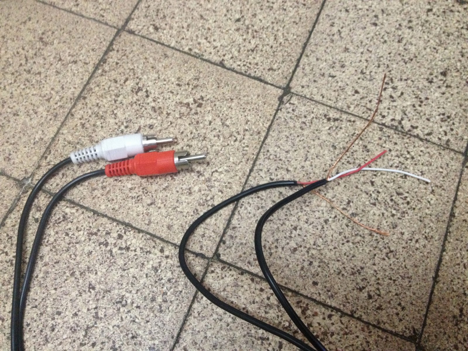
E60 Audio: RCA Feed from Rear Speakers - quick n dirty guide.

**Caution: This guide is for fitting extra component/coaxial speakers and is NOT suitable for fitting subs as the rear-speakers receive no low-end frequencies. If you are fitting subs then see THIS GUIDE on getting bass-RCA from the stock-subs.

This guide covers a very quick and easy way to get an RCA-feed into the boot on your BMW E60 and other iDrive models. This method is only suitable if you are fitting extra component or coaxial speakers [inc. 6x9s etc.] where the range of frequencies handled by the rear speaker-EQ are required.

PROCESS:

** If you are fitting extra component/coaxial speakers then adding a crossover-box to the RCA-feed before the amp should not be necessary. If you intend to use a crossover, substitute the 4 wires of the Red/White RCA-cable in this guide for 4 lengths of normal wire and see THIS GUIDE on how to install it.

1. Take a normal Red/White stereo RCA-cable, cut both plugs off from one end and separate the two wires down most of its length. An RCA-cable of about 4 feet should be plenty to reach up to both rear-speakers.

2. Carefully unwind the earth-wire from around each coated-wire and twist them off, so each of the coaxial RCA-wires is now split into two, as shown.


3. Bend each of the four wires over about 5mm from the end and completely sheathe the two bare earth-wires up to here, so they are well separated from the red/white live wires, as shown.


4. Gently prise off each rear-speaker grille using a flathead screwdriver, starting at the front edge.

5. Remove the 3 screws holding each rear-speaker using a T20 Torx-head wrench/driver, then lift out and unplug both speakers.

6. From inside the boot, light can be seen coming in through the empty speaker-recesses. Route one cut end of the RCA-cable up into each speaker-recess. They should easily be reached now from the parcel-shelf.

7. Splice the coated live-wire of the RCA-cable to the + speaker-wire on each side and the bare earth-wire to the - speaker-wires. The colours are as follows:

O/S - Yellow/Black +, Yellow/Brown -.
N/S - Black/Red +, Black/Purple -.


8. Push the wires down into the parcel-shelf and replace the speakers/grilles.

Done in 5 minutes!


Wednesday, 11 September 2013

E21 316: Fitting E30 rear sport-seats - or having a go anyway.

Stock fit works, but leaves big gaps.
As with the front seats I used HSVTurbos build [here] as a rough guide. His rear bench-seat is the all-sponge kind, whereas mine have the sponge base, but a sprung back-rest, possibly due to the folding arm-rest or model year difference. This means I have a metal frame to work with on the back-rest, so it can be pressed flat to greatly reduce the proud fit at either corner, but also means more needs to be cut away than just blobs of sponge. The E30 coupe's rear seat-pan, the body-tub and front doors are almost identical dimensions to the E21, so the rear seat-base just slots in. There are no brackets along the bottom-edge to clamp the squab down, but with it seated flat and wedged under the back-rest these may not be necessary, although fabbing some up might be worthwhile to stop the carpet sagging down in the footwells.

The general shape of the back-rest is more or less the same as the E21 and the hooks fit into the existing brackets, though the E30's parcel-shelf is curvier, causing the back-rest to stick out slightly at the top corners. The back-rest also sits slightly higher, leaving an inch gap at the bottom between it and the squab. If these gaps don't bother you then the seat works fine like this and will only need a little chopping off each upper corner to achieve a pretty good looking fit. If they do, then a little more work is required to seat the back-rest flush and minimise the corner gaps.

The main problem here are the seat-belt reels, which protrude from the bulkhead and fill up where the upper corners of the back-rest want to be. The back-rest bolsters are also slightly too broad, though the centre of the rear frame is more or less a perfect fit to the E21 bulkhead.

Modifying the Back-rest:

1. Bend up the small hooks holding the cover material in place over each side edge of the back-rest and pull the fabric clear of the metal frame.

2. Cut away the side-support on each side of the frame, leaving just the edge of the 'mattress' frame that holds the springs, as in the photo below. The brackets at each bottom corner should come away here too.

3. Cut in half the metal bar that runs between the centre and bolsters, the one attached to the top spring in each corner, and trim away the top spring as close to the frame as possible.

4. Cut the metal bar running along the top of the frame about 4" in from either top corner

5. Cut away the boar-hair matting along each side of the back-rest to reduce its depth by about half.

6. Cut a 2" square from each top corner of the boar-hair matting to give a recess where the seat-belt can run freely back into its reel.

7. Replace the fabric cover, hooking it to points on the mattress-frame and tucking it under the springs. At each top corner, I pierced a hole and ran a cable-tie through to hold the folded fabric clear of the seat-belt reel.

Fitting to the E21:

To get the back-rest sitting flush to the seat-base the original mounting-brackets may have to be abandoned in favour of slotting the hooks on the bulkhead directly into the top of the back-rest frame. The original lower brackets are attached to the frame here and may need cutting off for a tight fit.

1. Hook the top lip of the back-rest frame over the metal hooks on the bulkhead. Press hard to make sure the metal bar gets over the hooks and not just the boar-hair and fabric. Give each side a good knock down onto the hooks. The top of the back-rest should be about 5mm lower than the parcel shelf.

2. Fit the centre arm-rest and lock the clips into place. The back-rest should sit a bit proud of the bulkhead and need pushing flat. Drill two holes through the back plate of the arm-rest and bulkhead. Fasten it together with two bolts or pop-rivets. Not only will this hold the seat in place, it will also stop it moving when the arm-rest is lowered.