Showing posts with label M40. Show all posts

Sunday, 6 February 2022

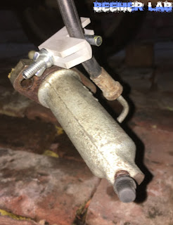
E30 318i: Replacing Clutch Slave-Cylinder - Quick + dirty guide!

Clutch reservoir suddenly low on fluid? Gearbox housing covered in it? Sounds like a popped slave-cylinder. Not to worry, this has to be one of the easiest to replace ever made!

* This guide covers the M40 engine and 5-speed gearbox, but process is the same for most models. *

1. Lift the left side of the car.

2. Remove the 13mm nut from the outer side of the slave-cylinder. This one is easy to access and can be got with a ring-spanner or socket, but the ratchet is quite snug to the gearbox.

3. Remove the 13mm nut from the inner side of the slave-cylinder. This is quite difficult to get to as it is inhibited by the clutch-hose as well as limited access in the trans.-tunnel. I managed it with a socket and a 4" extension bar to get past the hose/pipe. 

* I have seen someone getting that difficult to reach nut using a longer extension bar and the ratchet further back behind the gearbox, but this was not possible on my E30, so I'm guessing this may be for 4-speed boxes or older M10/M20 engines. If yours cannot be got with the details in step 3, then try this. *

4. Remove the slave-cylinder fr the gearbox and allow to hang down on the hose.

5. Clamp the hose (optional, but saves time when bleeding system later).

6. Remove the hose end from the slave-cylinder using an 11mm wrench so the old unit can be discarded. [It is much easier to grip the slave-cyl. by hand while it is removed from the gearbox and get a turn on the pipe-collar, as well as minimising leaks from the hose.]

7. Prime the new slave-cylinder by removing the bleed-nipple and carefully pouring DOT4 brake/clutch fluid into the hole at the top for the hose/pipe until the air is displaced and the fluid run out of the lower hole. It won't need much. Refit and tighten the bleed-nipple. 

8. Refit the hose-end to the slave-cylinder and remove the hose-clamp if you're using one.

9. Refit the slave-cylinder to the gearbox and tighten the two 13mm nuts.

10. Top up the clutch reservoir with DOT4 brake/clutch fluid and bleed the system of air. [Which bleeding technique you use is up to you, but for all BMW clutches I would recommend using a one-way valve attached to the bleed nipple as detailed in THIS POST, which saves time and headaches.]

Wednesday, 15 September 2021

E30 318i: Replaced AFM (Air-Flow Meter)

I’d been messing with my AFM in order to get the car running ok when cold and when I finally fixed the massive air leak on the inlet manifold I then struggled to reset the AFM back to standard. 
In order to get the M40 to idle ok while the engine was cold I adjusted the mixture setting to run richer. Obviously this was providing enough fuel to stop the engine cutting out while the plenum was filling with as much air as the cylinders could gulp through the gap in the manifold gasket. It runs and drives ok in this setting, but idles quite high (about 1100rpm) and you can smell the stink of neat petrol out of the exhaust. Ok for short trips shunting the project car around but will need addressing to enjoy it before summer ends!
The real problem began when I had repaired the gasket, got the engine running smoothly and then tried to reset the AFM back to a stock, or near stock value. To begin with I had been putting marks and taking photos to recall where the settings were before I started messing, but you know how it is, once you get immersed into a several day long tweaking session (take that as you will!) the tendency is to get lost along the way.
I gave up trying in the end and decided the only way to dial this engine in and be sure I was not fighting with a dodgy AFM was to buy one that had not been messed with. This is in my interests anyway, as I got one from a car with far lower miles on it so the carbon-track is less worn and I know the air-temp sensor is OK too, which was a doubt with the original one.

Sunday, 29 August 2021

E30 318i M40b18: High / erratic idle issues NOW FIXED, stable at 800rpm + good throttle-response finally

After my cutting out when cold problem and no low-end throttle response from a busted lower inlet-manifold gasket (THIS POST) and high / pulsing idle issue from a poorly set throttle-stop screw (THIS POST), I have finally got the old E30 ticking over properly. It now sits at about 800rpm on idle and throttle response is smooth across the range. Pleasant.

Wednesday, 28 July 2021

E30 318i: Leaking clutch slave-cylinder... fluid low


Now the E30 is running well I took it out for a test run and noticed that all of a sudden the gears were grinding a little bit. Checked the fluid reservoir and the level had dropped to about 10mm, not good. Looked under the car and saw a spot of fluid on the drive right under the slave-cylinder. My guess, and no prizes for guessing right here, it was a leaking slave-cylinder and, hey presto... sure looks like one to me.

Replacement is ordered. I went for a cheap and cheerful one off eBay for just £16.50, though £25-40 seems to be the going rate. Be fitting this when I have chance. Looking forward to the bodywork, but mechanical jobs just keep popping up... that be old BMWs!

Monday, 26 July 2021

E30 M40 316i / 318i: Adjusting Throttle-Body and Idle Stop-Screw

Yes, this is set at the factory and they say it should never be messed with, but as the youngest M40 engined BMWs are approaching 30 years old now, chances are the stop-screw and throttle-plate will have been adjusted at some point in its life. 

Here I will explain what happens when it is adjusted, the problems it may cause if it has been and how to reset it back to stock. 

WHY HAS IT BEEN ADJUSTED?

The stop-screw should have a paint mark on it from the factory to show if it has been messed with, but after so many years the mark may no longer be visible. If you feel yours has been adjusted in the past, the main reason this has been done is likely to falsely raise a low idle caused by another issue, say an induction air leak. If an over lean mixture is causing a low idle, the tendency is to tweak the idle stop-screw to get the car to tick over at higher revs and stop the engine stalling out or running lumpy. This is a great short-term workaround, but will cause other issues with the AFM / DME and fuel delivery further down the line, particularly when the underlying issue is worked out.

SYMPTOMS:

The issues you will get with a poorly adjusted throttle stop-screw are:

High idle.

Hunting / pulsing revs. 

Poor or no low-end throttle response.

Erratic idle (if throttle position switch TPS is not engaged).

Bogging at high revs (where wide-open throttle WOT switch is not engaged).

ADJUSTING:

There is only one way the throttle can be adjusted, via the stop-screw, though the throttle-cable itself can be adjusted to change throttle response somewhat, mainly with how the pedal / cable reacts to driver input and will not affect the fuel/air ratio and the engine idle.

** The intended job of the idle stop-screw is simply to stop the throttle-plate from jamming in the throttle-body and being difficult to open when the pedal is pressed and not to change the car’s idle characteristics. BMW recommend that this is never played with, so do so at your own risk. **

1. Back off the lock-but using an 8mm wrench.

2. Use a small flat screwdriver to wind the idle stop-screw in and out. 

* Clockwise will push the throttle-linkage further from its rest position, holding the throttle-plate open slightly and allowing more air to bypass it while the pedal is not pressed.

*Anti-clockwise will allow the throttle-linkage to close further and will reduce bypass air and choke the engine while the pedal is not pressed. 

STOCK SETTING:

You will need a set of A/F / imperial feeler-gauges as this is how the stock throttle-plate aperture is measured. 

** If you are only adjusting the throttle-plate and do not need to adjust the throttle position switch (TPS) then the throttle-body itself does not need removing and you can skip to step 7.**

Removing the Trottle-Body:

1. Remove the main air-inlet hose from the AFM to the throttle-body by loosening the jubilee-clip and easing it off.

2. Unclip the throttle-cable from the throttle-linkage and remove the two screws holding the throttle-cable mount from the top of the throttle-body housing using a 10mm wrench. Move the cable assembly to one side.

3. Remove the two water hoses and air vacuum-hose from either side of the throttle-body by undoing the jubilee clips and teasing the hoses off with a screwdriver.

4. Remove the six nuts from the upper inlet-manifold using an 11mm wrench and the two locating screws from the manifold using a 10mm wrench. Lift the upper inlet-manifold so that the throttle body can be fully accessed. 

5. Remove the throttle-body from the inlet manifold by undoing the four nuts using a 10mm wrench.

6. Turn the throttle-body upside down and remove the throttle-position-switch (TPS) by removing the wiring connecter and undoing the two cross head screws.

7. Back off the lock-nut of the stop-screw using an 8mm wrench. 

8. Use a small flat screwdriver to adjust the throttle stop-screw by the notch in the end of it. Obviously, clockwise will move the screw further out and make the throttle-butterfly rest in a more open position. Anticlockwise will allow the butterfly to close more.

9. For the OEM setting, the throttle-butterfly should be 0.377” from the housing, so use your feeler-gauge between the side of the tube and either side of the butterfly until you find a happy medium.

10. Tighten the lock-nut up again with an 8mm wrench.

11. Now take the throttle-position switch (TPS) and locate it back in the housing so that the switch is depressed while the throttle is in the fully closed position. With the two screws loosened, the TPS can be swivelled left and right as in pic below to adjust the point at which it engages. The ideal placement for the switch is to have it click closed while the throttle is open about 1mm. (You will hear the quiet click from the TPS as it opens and closes.) When you’re happy with the TPS placement tighten the screws to lock it in place.

12. Before refitting the throttle-body, check the operation of the butterfly and TPS and make sure the butterfly is not binding to the body while fully closed as this will ruin low-end throttle response.

13. Refitting is a reversal of steps 5-1.

Wednesday, 9 June 2021

E30 318i M40: GUIDE - Replacing lower inlet-manifold gasket - rough idle and stalling fixed!

After all the diagnosis and testing from THIS POST, I found the cause of my rough idle and stalling out when cold was a damaged paper gasket on the lower inlet-manifold allowing unmetered air to be drawn in to the plenum at will and confusing the AFM and DME over how much fuel to deliver. 

The engine just about ticked over when warm, albeit with a slight misfire. On cold startups however, the misfire was a lot more severe and at low revs the engine just couldn’t hold on, stalling out due to a way over-lean mixture. It would drive though, but there was no throttle response until about halfway up the rev range and power would arrive with a bang. It is amazing how sensitive these older engines with analog electronics are to unmetered air leaks!

IF YOU HAVE THESE SYMPTOMS, CHECK HERE!

I ordered a new gasket from eBay, it was a snip at £6.88. Be careful when ordering, older M10 engine gaskets are far more plentiful, so ensure yours is the right one for the M40... they have a funny shape which is quite distinctive. Choice was limited, in fact I could find one more gasket for sale of the right type and that came with a full £30 set including a head gasket, so be sure to check out carpartsinmotion, they have rare-fit stuff.

GUIDE:

1. Undo the jubilee-clip and disconnect the large rubber duct from the throttle-body using a flat screwdriver or 7mm socket.

2. Unclip the throttle-cable from the throttle-linkage and remove the two 10mm screws holding the metal plate to the throttle-body so the cable assembly can be moved clear.

3. Remove the wiring connectors from the throttle position sensor [TPS] and idle control valve [ICV].

4. Remove the rubber hose from the bottom of the ICV.

5. Remove the vacuum air hose from the front side of the throttle-body by undoing the jubilee-clip and teasing it off carefully with a flat screwdriver.

6. Remove the two coolant hoses from either side of the throttle-body by undoing the jubilee clips and teasing them off with a flat screwdriver. 

7. Remove the six nuts from the upper inlet-manifold using an 11mm wrench [9 in diagram] and two locating studs in the centre with a 10mm wrench [13 in diagram]. 

8. The upper inlet-manifold can now be lifted out of the engine bay.

9. Remove the wiring connector from the fuel-rail / injectors. 

10. Remove the metal fuel send and return pipes from each end of the fuel-rail by undoing the jubilee clips. (This is where it gets messy, you may wish to plug or clamp the ends of these hoses). The send pipe is attached to the fuel pressure regulator [FPR] at the front of the fuel-rail and the return pipe is at the back of the rail.

11. Remove the five nuts holding the ports of the lower inlet-manifold to the head using an 11mm socket [4 in diagram].

12. Remove the two bracing bolts from the lower inlet-manifold using a 13mm socket. (They point towards the right side of the car) [11 in diagram].

13. The lower inlet manifold is now free to be removed. This can be a bit tricky as the rigid fuel pipes are routed through one of the gaps in the manifold ports. Also make a note of how the hoses to the throttle-body are routed through around the lower manifold, as it can be confusing once the upper manifold is bolted back in.

14. Clean off the mating surfaces of the cylinder head and the inlet manifold.

15. Carefully fit the new gasket to the studs on the head. It only fits one way round.

16. To refit reverse the above steps.

Sunday, 6 June 2021

1988 E30 318i Project - Check List:

 I will update this and cross things off as progress is made:

  • Straighten steering wheel.
  • Speedometer / Odometer inop.
  • Temperature gauge inop. [THIS POST]
  • Washer-jets / pump.
  • No hot air from heater-blower. [THIS POST]
  • Central locking malfunction.
  • Instrument lights flicker / dimmer function inop.
  • Clock inop. [THIS POST]
ENGINE:
  • Rough idle / stalling when cold. [THIS POST]
  • Exhaust too loud. [THIS POST]
  • Clutch slave-cylinder leaking.
BODYWORK:
  • Paint NSF wing.
  • Repair rear valance.
  • Touch up valance corners.
  • Panel above rear lights.
  • OSR wheel arch.

E30 318i [M40]: Massive air leak SOLVED - lower inlet-manifold gasket

I had checked and re-checked the idle control valve [ICV], the air-flow meter [AFM], ignition system, tested for the fuel pressure, performed tests on the DME [ECU] to make sure that was working and even laboriously tested the wiring loom for continuity, but still the engine idles terribly when cold. It ticks over lumpy, shakes the engine side to side and cuts out at will, even when power is applied. 

I checked the timing and all was good, under the rocker-cover showed no defective valves and the cam-shaft doesn't look all that worn. I guess the only thing left to check is the injectors... right?? Now hold on a minute I hear the E30 and M40 engine gurus cry, the symptoms you've described point towards an obvious massive air leak in the induction system! 

This is true and is also the very first thing I looked for and tested. Initially I performed the 'spray' test using a can of brake-cleaner (though 'Easy-start', carb-cleaner or electrical-cleaner work too, anything with alcohol content). This involves running the engine and spraying brake-cleaner around the intake-manifold, ICV, vacuum hoses, throttle-body etc. If unwanted air is being sucked in, say through a split hose, the brake-cleaner will be sucked in and combusted by the engine causing it to rev higher. If you are spraying in one particular place and the engine revs increase accordingly then you have found your air-leak. Thing is, I did this test over and over again and it showed nothing. 

I’ve heard that air can be sucked in past the injector bodies when the rubber sealing rings have degraded over time and that the lower intake-manifold is also a main culprit, but spraying round this area made no difference to the engine revs or affected the poor idle. I did a compression test and the readings were a bit low, but not enough to cause any issues.

At this point I decided it to bite the bullet and begin stripping things down. The removal of the lower intake-manifold is quite complicated because it involves removing the fuel-lines from the rail, which is why I put it off, but clearly if you want to fix something then you need to get your hands dirty so off came the fuel lines and away came the lower manifold to reveal.... well, as you can see from the photo, a virtually non existent gasket. Sigh. 

Cylinder 1 has a massive gap where the gasket is no longer there, so whenever there is a vacuum in the plenum it’s just filling up with fresh air even with the throttle-body shut and this explains why the ICV appears to be doing nothing and leads people to look there first. Whoever was refitting the manifold was obviously in a rush because the broken gasket has folded over on itself, causing the air gap to be even bigger. I guess they just tightened it hoping to make a seal, but alas no. Cylinder 2 is not much better with a noticeable gap and the rest of the gasket squashed flat. Cylinders 3 and 4 are better, but still paper thin. It looks like this may be the original gasket and the past 35 years have not been kind to it (or to me for that matter).

So... looks like I have found the culprit of the rough idle. Finally! New gasket is ordered, a snip at £6.88! Amazing how such a simple thing can cause such a severe problem and goes to show how sensitive these ‘analog’ ‘80s cars are to air metering issues!

Saturday, 5 June 2021

E30 318i: Correct Temperature Sensor fitted (Brown Plug) + wiring/loom issue

The temperature gauge in the dash has not worked since I bought the E30, which was a little worrying on my 250 mile drive home, but the car does not overheat. Oh, it has some issues with the cooling-system, like the heater-matrix pipes fitted incorrectly and an air-lock at the back of the head, but hey it doesn't overheat. Still though, I thought it best to get the bottom of the faulty temp. gauge for peace of mind, particularly with summer coming / just about here.

The M40 has two separate temperature sensors that are independent from one another. The temperature gauge works from the 'Brown plug' sensor to the rear of the head [right in pic]. The forward sensor is the 'Blue plug' [left in pic] and that connects only the DME (ECU) to tell the car if the engine is cool or warm to help with cold-start procedures. A single sensor cannot be used for both purposes on these older engines as the resistance value ranges required for each function differ, the DME being a digital circuit and the temp. gauge still working in analog. [You can read more about this on the E30 Zone Wiki HERE].

MULTIMETER TESTING:

The temp. sensors can be easily tested with a multimeter set to 20k ohms resistance. 

The Blue plug is a two-pin sensor, so test across both terminals with the multimeter and you are looking for a reading of 4-4.5k ohms for a working sensor. This sensor and plug can be accessed easily without removing any parts from the engine.

The Brown plug though will require removal of the lower inlet-manifold to access the sensor for testing or replacing. This is a single pin sensor, so place one probe of the meter to the terminal and the other to a ground-point in the engine bay or against the block/head. Expect a reading of between 1k and 1.5k ohms for a working sensor. To test the Brown plug sensor without removing any parts from the engine, you can apply the multimeter to Pin 4 of the C101 connector (main wiring loom plug in engine bay) which is easy enough to get at, or at Pin 26 of the blue connector to the right side of the instrument binnacle, though the binnacle will need removing to do this.

WRONG SENSOR / CONFUSING WIRING LOOM:

All M40 engine wiring looms use a single pin temp. sensor on the brown plug that earths through the engine block and have only a single wire in use leading to it. Some looms, using components destined for other BMW models, are known to have a second wire leading to the Brown plug temp. sensor which is redundant on the M40 motor, though this is rare and seen more often on 6-cyl. M20 looms. My car has one such loom, however and I realise that this is what has caused confusion in the past and led to the wrong sensor in fact being fitted...

Upon inspection, the rear temp. sensor fitted to my E30 is black, not brown and has two terminals. The second pin means that the sensor body earths back to the loom and not through the block so, if the redundant earth wire in my loom is not connected to a ground-point then the sensor was open circuit. I guessed that someone had ordered a second Blue plug sensor by mistake and fitted that, but it turns out the part number doesn't match and the sensor is for a completely different model engine entirely. The reading from the multimeter was over 11k ohms, something like 7.5 times what it should be! That sensor was never going to work with the E30 temp. gauge circuit whether it was earthed or not.

I ordered the correct single-pin sensor with the brown base from mr-wiper on eBay, who also supplied my Bosch spark-plugs. It was only £7.69 delivered. My temp. gauge now works, but this may also be due in part to removal of an air-lock at the back of the head due to a heater-matrix problem so coolant is now flowing properly round the area of the sensor. 

A BIT MORE ON WIRING LOOMS:

Brown / Violet, brown being the main colour, denotes that the power source provided from the temp. gauge circuit is earthing through this wire and does not need to be a closed circuit back to the gauge. The other wire is either not wired in to the loom or goes to a body-earth anyway, so earthing the sensor through the block will make no difference. This colour coding is the same for all wires in all BMW looms, I would imagine most cars are the same.

Monday, 31 May 2021

E30 318i M40: Bosch injectors and tips - checking condition

Next on the agenda to find the culprit of the rough running and stalling idle was to examine the injector condition and the plastic tips. The injector bodies are quite rusty and corroded so they could well be the original set, but on closer inspection the tips are fine and they look to be in pretty good condition, so onwards.

To inspect the injectors the lower inlet manifold will need to be removed, which involves de-plumbing the fuel lines and some of the water hoses. 


E30 318i M40: Camshaft and valve condition

I whipped the rocker cover off to check if there was a dropped valve or broken spring that might be contributing to the poorly idle, but no such defect found. In fact, this has to be one of the cleanest top ends I have ever seen. Nice!

E30 318i M40: Misfire and self-revving - symptoms of major induction air-leak

This video shows the symptoms of an air-leak in the induction system, where unmetered are drawn in after the throttle-body causes a terribly poor idle, a permanent misfire and the engine to rev itself gently. The tendency is to look at the ICV (idle control-valve), ignition coil, AFM (air-flow meter) etc., but chances are it will be an air-leak on the induction. In this case it turned out to be a damaged and disintegrated gasket where the lower inlet-manifold mates to the cylinder-head. 

Sunday, 30 May 2021

BMW E30 Heater Matrix Hoses Configuration - Right and Wrong way round + how to bleed matrix / remove air-lock

My E30 had little or no hot air from the blower inside the cabin. I have heard it is common for the two hoses running to the heater matrix to be fitted back to front, so the flow of coolant through the core is reversed. This causes air locks and severely reduces the amount of coolant flowing through the heater matrix, thus no hot air. 

The reason these hoses so often get fitted incorrectly is due to their location and the way they look when fitted. It appears obvious that the upper hose (back of cyl.-head to heater) goes to the upper stub on the heater-matrix and the lower hose (side of block to heater) goes to the lower stub on the matrix. The hoses look happier this way round, but the matrix and heater-valve are designed in such a way that flow is interrupted and causes the air-lock. 

The correct way round is actually with the upper hose connected to the lower stub and the lower hose to the upper stub, which does of course appear to be back to front, but is essential for correct flow of coolant round the whole engine, not just the heater-core. The correct and incorrect hose configurations are shown in the pictures below.

RIGHT:

WRONG:

How to Bleed system and remove air-lock from Heater-Matrix:

** This is not the normal air-bleeding process when refilling an empty system with coolant, this process is to bleed a system with the air-lock at the back of the head and / or the heater-matrix full of air. **

1. Ensure heater-matrix hoses are fitted the correct way round, if not swap them over. [You should notice if there is an air-lock that no coolant comes out of the hoses when removed from the matrix and the stubs appear dry].

2. Fully tighten the lower [inlet] hose.

3. Leave the upper hose disconnected from the matrix. 

4. Remove the radiator bottle cap. Assuming the coolant level is up to the halfway / max. mark, there should be some gulps of air and the coolant level should drop slightly in the rad. bottle.

5. Cut the bottom off a 2-litre drinks bottle and fill it with water, holding your hand over the lid.

6. Dump the water from the drinks bottle into the radiator bottle, allowing the weight of water to push the remaining air though the system. Water should start to come out of the upper heater-matrix hose from the head. Block this hose with a finger.

7. Continue to top up the radiator bottle with water until water begins to flow out of the upper stub on the heater matrix and quickly refit the upper hose, which can now be fully tightened.

8. Drain the radiator bottle back down the halfway /max. / fill line.

** You should be good to go, but can now bleed / top-up the system using the usual bleeding procedure if necessary. **

Wednesday, 26 May 2021

BMW M40 Engine - how to check timing, where the marks are located

This must be one of the hardest bits of info to find in the whole world of BMW, but there is a great post on BMW Werks on how to do it [https://www.bimmerwerkz.com/threads/m40-motor-timing-info.59059/].

QUICK TIMING CHECK GUIDE:

** Only if crank pulley has NOT been separated from crankshaft! **

1. Remove the distributor / timing cover at the front of the engine.

2. Check the timing mark on the crank pulley. This is an arrow cast into the block which should line up with the sprocket tooth to the right of the gap in the teeth, as in pic below.


3. Check the timing mark on the camshaft pulley. This is a notch/line mark in the pulley and should line up with the right-angle notch in the cylinder head, as in pic below. If this looks good, your timing is fine.


Thanks again to xdrian on BMW Works for making these pics and sharing this secret!

Monday, 24 May 2021

E30 318i: New Bosch spark plugs + correct coil fitted

With the car still misfiring a bit, I turned my attention to the plugs and HT leads. All appear fine. The coil works because there is a spark. I inspected the plugs, a set of NGK R that don't look particularly ancient, expecting one or more to be wet with unburnt fuel from a combination of misfiring and running an over-rich mixture from tweaking the air-flow meter [AFM]. I noticed that the plugs were in fact all dry and totally black with soot at the tips from over-fuelling, but their condition seemed fine. This matched the points in the distributor-cap, which were also blackened.

The spark plugs were working, but they didn't seem to fully igniting the mixture and performing weakly, so I turned my attention back to the coil. A previous owner had fitted a universal 'Sports coil' and judging by the shiny casing it doesn't look too old, so I couldn't see how it could be at fault. Thats when I noticed the terminal connecting it to the HT lead. It's about 10mm wide and has a metal inner lining. There is a screw at the bottom holding it in. This is obviously designed for a different type of HT lead than fitted to BMW, as the lead has a rubber plug where

it contacts the copper casing of the terminal in the coil. The metal terminal in the HT lead is designed to fit over a stud inside the coil-terminal, which is what I've always seen before, not just in BMW. This means the only contact being made by the main HT lead was its very tip touching the screw at the bottom of the coil-terminal.

I swiftly ordered a used OEM Bosch coil unit from eBay for £15. A 'Sports coil' type with the correct end was about £35, but I figured it was best to go original, at least for the time being while I iron out the M40 engine's running problems. While I was at it, I bought some OEM Bosch spark plugs for £13, which is cheap and I thought I may as well rule out plug condition as a factor with not knowing how long the incorrect coil has been fitted to the E30. 


Saturday, 24 November 2018

BMW Tightening Torques [PDF]

Superb 136-page document from BMW showing the tightening torque for every different bolt / screw on your car. It covers generic torques for all BMWs, as well as model specific ones for petrol, diesel... even the V12.

https://drive.google.com/open?id=0B1JGYWCqjPsqSTBWRGZYdFBLS3c


CONTENTS:
  • General Instructions
  • Engine
  • Engine Electrical
  • Fuel System
  • Radiator
  • Exhaust
  • Clutch
  • Transmissions and Drivetrain
  • General Electrical
  • Instruments
  • Equipment Accessories

GENERAL TORQUES:
M4 8.8 - 2.9 Nm
M4 10.9 - 4.1 Nm
M4 12.9 - 4.9 Nm
M8x1 8.8 - 26 Nm
M8x1 10.9 - 36 Nm
M8x1 12.9 - 44 Nm
M14 8.8 - 130 Nm
M14 10.9 - 180 Nm
M14 12.9 - 220 Nm
M5 8.8 - 5.9 Nm
M5 10.9 - 8.3 Nm
M5 12.9 - 10.0 Nm
M10 8.8 - 47 Nm
M10 10.9 - 66 Nm
M10 12.9 - 79 Nm
M14x1.5 8.8 - 143 Nm
M14x1.5 10.9 - 200 Nm
M14x1.5 12.9 - 240 Nm
M6 8.8 - 9.9 Nm
M6 10.9 - 14.0 Nm
M6 12.9 - 16.5 Nm
M10x1 8.8 - 54 Nm
M10x1 10.9 - 75 Nm
M10x1 12.9 - 91 Nm
M16 8.8 - 200 Nm
M16 10.9 - 280 Nm
M16 12.9 - 340 Nm
M7 8.8 - 14.8 Nm
M7 10.9 - 21.3 Nm
M7 12.9 - 25.5 Nm
M12 8.8 - 82 Nm
M12 10.9 - 115 Nm
M12 12.9 - 140 Nm
M16x1.5 8.8 - 216 Nm
M16x1.5 10.9 - 303 Nm
M16x1.5 12.9 - 364 Nm
M8 8.8 - 24 Nm
M8 10.9 - 34 Nm
M8 12.9 - 40 Nm
M12x1.5 8.8 - 87 Nm
M12x1.5 10.9 - 123 Nm
M12x1.5 12.9 - 147 Nm
M18 8.8 - 280 Nm
M18 10.9 - 390 Nm
M18 12.9 - 470 Nm
M18x1.5 8.8 - 313 Nm
M18x1.5 10.9 - 440 Nm
M18x1.5 12.9 - 527 Nm